project finished created updated
Tinykb
Designing and fabricating a portable split ergonomic keyboard for small hands — with zero electronics background and a lot of help from the Ergogen discord.
Specs
- Switches: Choc v2
- Layout: split, aggressive column stagger
- Wireless — Nice nano mcu + nice nano display
- Software: Ergogen (layout) → KiCad (routing) → JLCPCB (manufacture)
- Config repo: tinygg on GitHub
- Status: finished (v6)

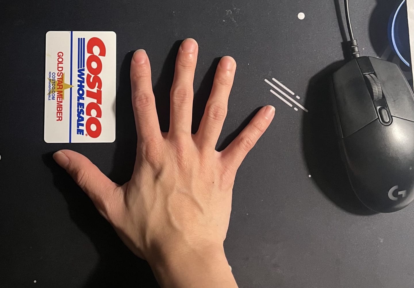
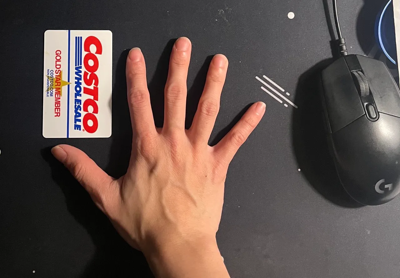
I have really small hands and have developed bad wrist pain over recent years despite trying to fix my posture, setup etc. Most mechanical keyboards aren’t really designed for smaller hand sizes like mine. I felt the most pain in-between my pinky and ring finger, which I found was because of how far key travel is. This is what got me into the keyboard hobby, unfortunately.
My first keyboard

My first keyboard was a ducky shine ii (a very old keyboard!) with a full 108 key layout. This is the keyboard that got me into the hobby and interest in testing out different layouts, switches, and switch weights.
My current keyboard
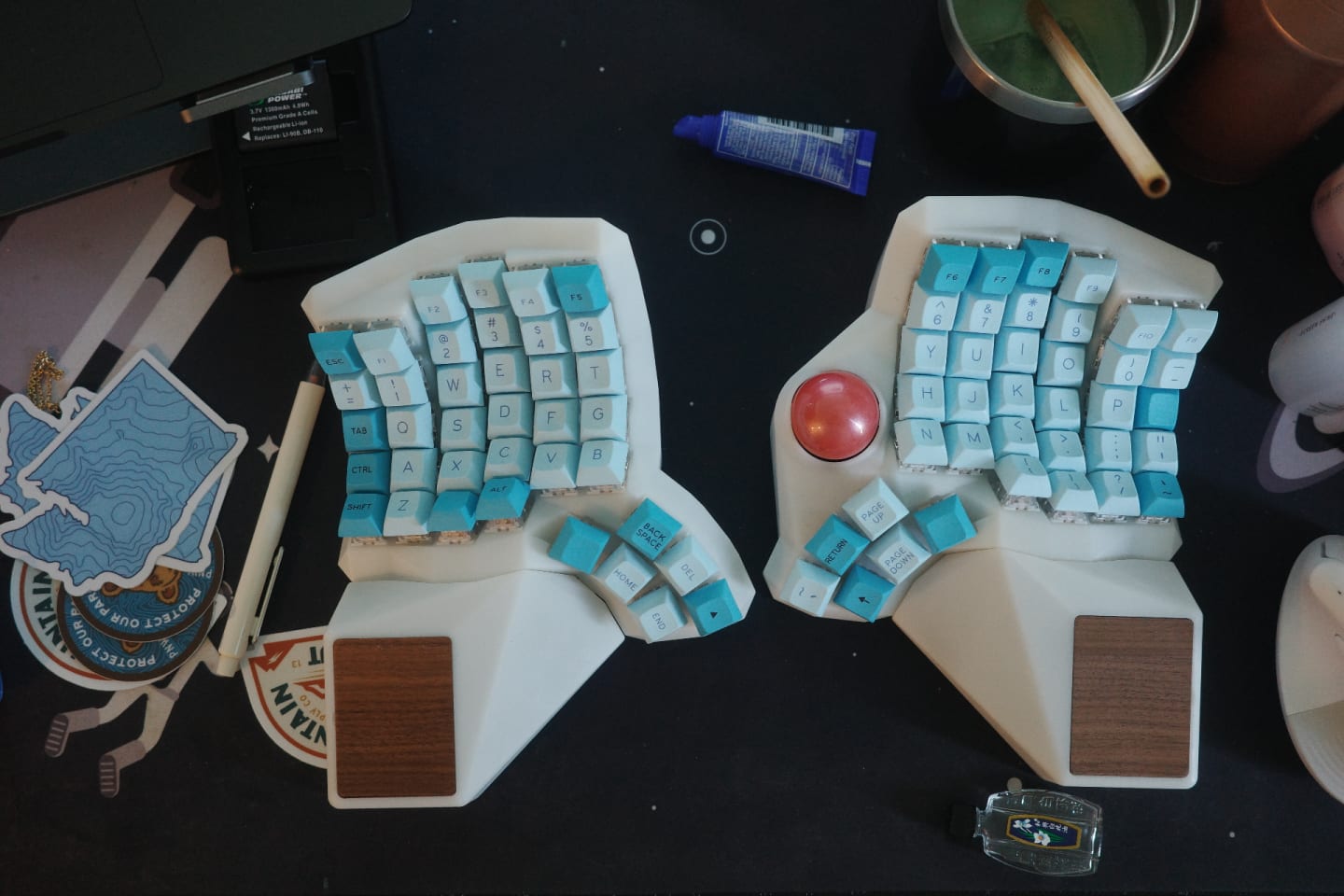
This is my current keyboard! It looks goofy but it’s probably one of the things I’d save if my house caught on fire. It’s actually made to my hand size, it’s 3d printed resin and one of the reasons I’m in this class!
Unfortunately… I can only use it at home. The material isn’t as sturdy as other easily purchased keyboards, so I really don’t want to transport this around. So… I decided for my final project to create a portable ergo keyboard!
To get the requirements out of the way, I’ve highlighted the techniques that I used for this project. The rest of this will be a chronological account of building the keyboard.
My requirements
- It should “portable”
- Wired
- Ergo
- Sturdy enough to bring around
Project requirements
- Use four of the following:
- Laser cutting
- Rhino
- Grasshopper (kicad in my case)
- CNC milling
- 3D printing
- Interference fits (press-fit)
- Incorporating stock parts
- Mold design
- Combination of:
- Coherent concept
- Good execution (hopefully)
- 2D/3D designs
- additively fabricated parts
- subtractively fabricated parts
- cast parts
- high quality finish (hopefully)
Goal
- Design and fabricate a keyboard for my hand size
- Fulfill requirements for the assignment through iterating materials in the process
- Does not include:
- ZMK working config - as long as the keyboard is assembled the project would be “complete”
- Contingency: keyboard case
Stretch goals
Inspiration
Elora
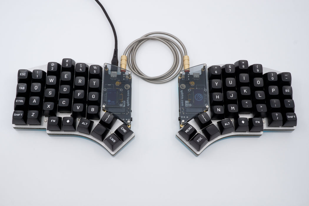
I was going to buy this keyboard to take around, but like most great keyboards…
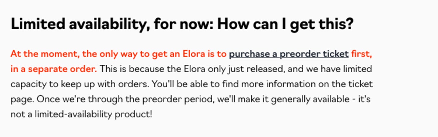
So…. DIY?
At first, I was contemplating buying one of the PCBs of kyria v1 (one of their older keyboards) but I came across this video:
“The REAL Ergonomic Keyboard Endgame!” - How To Design & Make A Totally Custom Keyboard
The creator used an open-source package called Ergogen to generate their own keyboard layout. The output files also generate a PCB file you can open in KiCad to finish routing then send out to have manufactured.
Designing with Ergogen
tsteffek/Ergogen-V4-Migration-Guide: Migration guide from Ergogen v3 to v4
So far, I’ve iterated over the shape I want and decided what specs I want my keyboard to have.

Unsurprisingly, getting the layout was only the start of a lot of googling. I ended up joining their discord and I practically lived in that server for two weeks.
As I continued designing the shape of the keyboard, there were some limitations - it was difficult to get the extra parts added to the pcb. Things like the power switch, the microcontroller and the battery dimensions had to be added to the design of the board. So, I ended up installing ergogen locally:
npm i ergogenOnce I installed it, I created a new folder for this project, initialized git, and added the following community created footprints as submodules I could use:
git submodule add git@github.com:infused-kim/kb_ergogen_fp.git ergogen/footprints/infused-kim/

git submodule add https://github.com/ceoloide/ergogen-footprints.git ergogen/footprints/ceoloide
Then I created a config.yaml file in the folder project and running:
ergogen . config.yamlMy full layout config (config.yaml) lives in the tinygg repo on GitHub.
I then used KiCad to view the pcb and start routing. I should probably disclaim this again and say I have no experience whatsoever in electronics… at all. Like zero. Don’t know what a ground and short is. So I decided I would just learn what I needed to get this working.
This was my first layout:
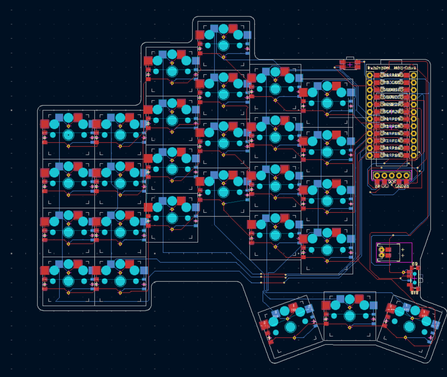
To start, I copied someone else’s routing file, and just changed it by adding an extra number row just to get myself started. I was feeling pretty confident until I ran Design Rule Checker…

109 violations. OOF. I went off to discord to ask the community about these errors - turns out a lot of them were about the clearance issues that I setup in board constraints, and some unconnected items of front and back plate. In an effort to save money, I decided to design a reversible pcb - which means I could use front side as left side, and back side as right side. This gave me a LOT of heartburn. There are things that ned to be set up and decided - is the mcu facing up or down, is the battery facing up or down. Aside from this, I forgot to add mounting holes to my pcb. Rookie mistake.
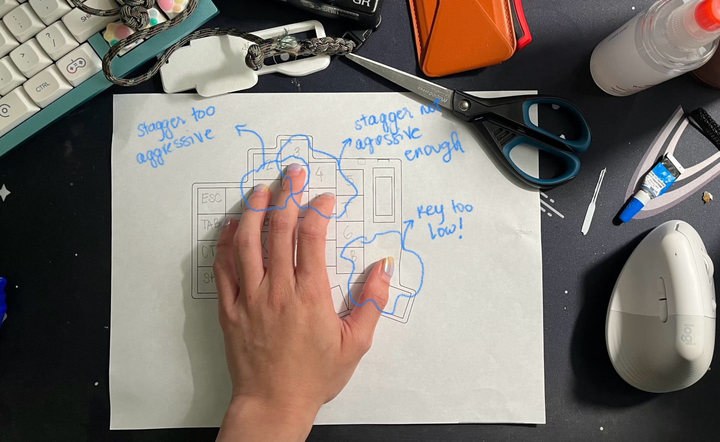
The improved thumb placement


Starting from zero again this far into the process was difficult, but I guess that’s the point. Anyway, as shown in the photos, I fixed the stagger units for ring->middle and middle -> index, as well as extended the thumb keys to the side and removed one of the cluster keys.
I also rearranged the mcu, power switch, reset switch, battery pack and added mounting holes near the bottom of the mcu so I could place a cute arcylic cover over it when I make the case.

The switch size for 1.25u keys is the same as 1u so it’s not so obvious yet that the keys in the thumb portion will be bigger (but they will be!). I ended up adding another via per key to fix the unconnected portion of the front and back plate.
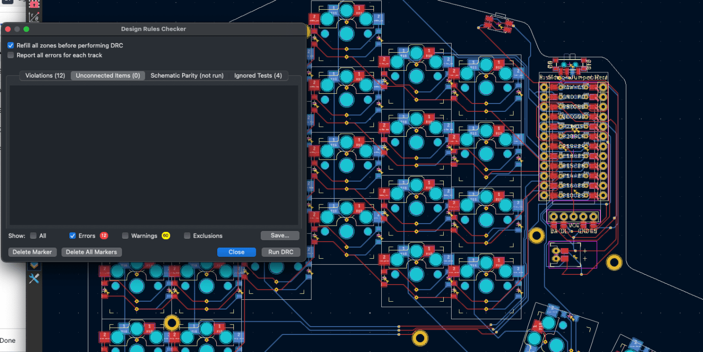
Woohoo!! Finally no unconnected items. The 12 violations are about the mcu clearance violations but that can be ignored. I switched up the layout of the mcu, power button, reset switch and battery after looking at even more pcbs.
IMPORTANT: DO NOT* FORGET TO SET UP THE BOARD TO CONSIDER MANUFACTURER CONSTRAINTS!
So pretty!!
After running all the checks, I did run to discord once more to see if anyone was willing too check my board pcb. The ergogen community is SO supportive and welcoming (unlike other keyboard communities), and someone actually was able to download my pcb file and check my routing. I appreciate them so much.
After finishing my main board, I toyed between printing the backplate and switch plate in FR4 and and adding them to my order, but I decided to keep it simple instead and use those plates to try different fabrication techniques required for the project.
I uploaded to JLCPCB, and now the waiting time begins!
The final keyboard specs:
- Choc v2 switches
- Split, aggressive column stagger layout
- Wireless
- Nice nano mcu, nice nano display
Deciding mounting
Different mounting styles
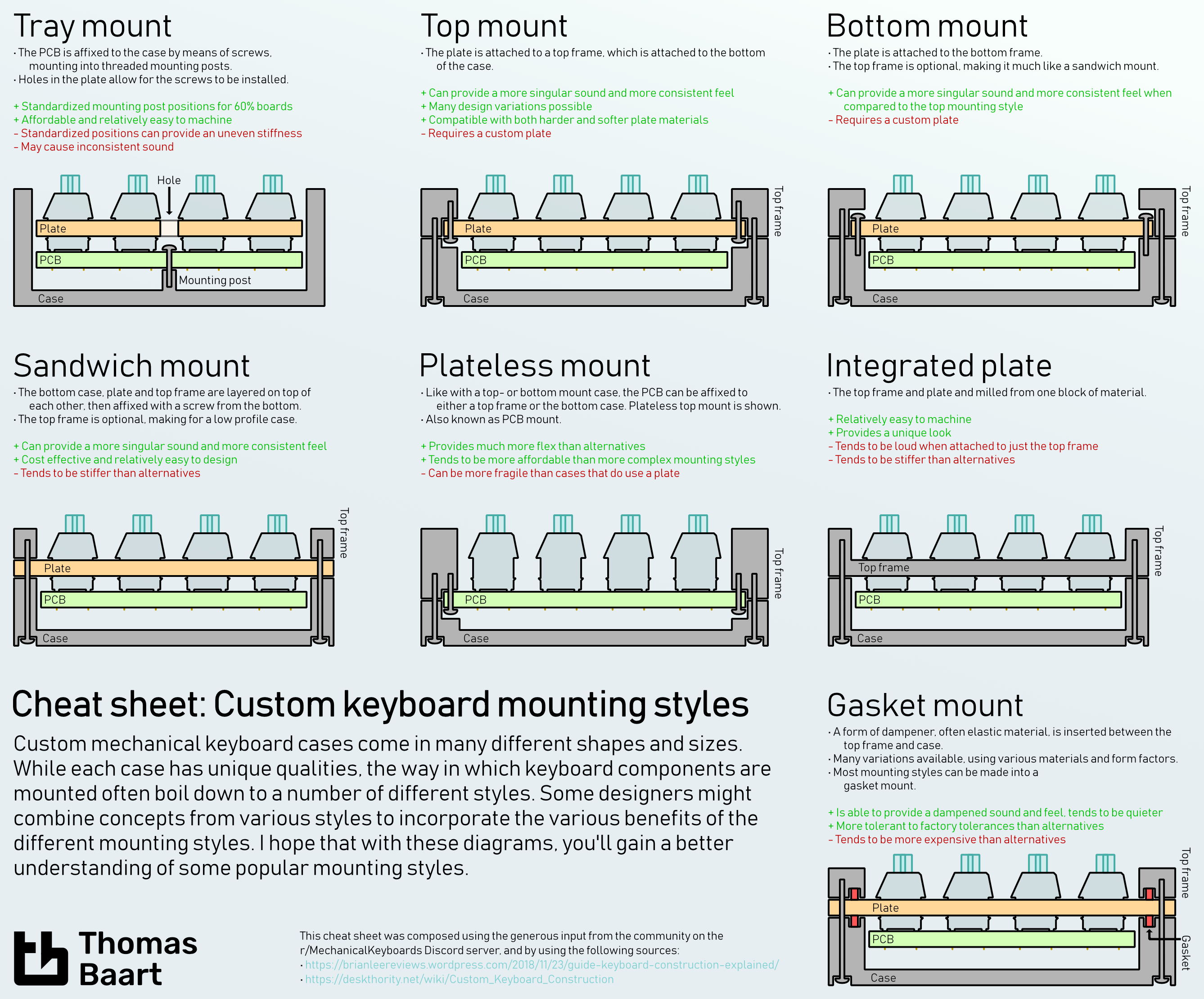
From the ErgoMechKeyboards community on Reddit: Custom cased Kyria
Ideally I would’ve had RGB but I decided not to complicate my life even more, so I kept it out of this build. I plan to do the simplest mounting style (the sandwich), which consists of attaching the pcb to a top plate (switch plate) and bottom plate.
Keycaps
While waiting for the PCB to arrive, I decided to 3d pint some keycaps. I went to a keyboard meetup with flo once, where someone had keycaps that had a depression in the center, making it easier to “feel” the keys. It looked something similar to this:

Of course naturally, I didn’t want to pay $54 for the key set. I figured if I’m not the first person to want to buy these keycaps, so I went in search for a project on GitHub that might have stls for this. I did find a few like the https://github.com/infused-kim/kb_keycaps_chicago_stenographer, but unfortunately nothing like what is seen in the top photo.
I was able to prototype something close to those, but due to the interest of time, I only printed one. I will print the rest when I have time to figure out the right settings to get the lines less obvious.
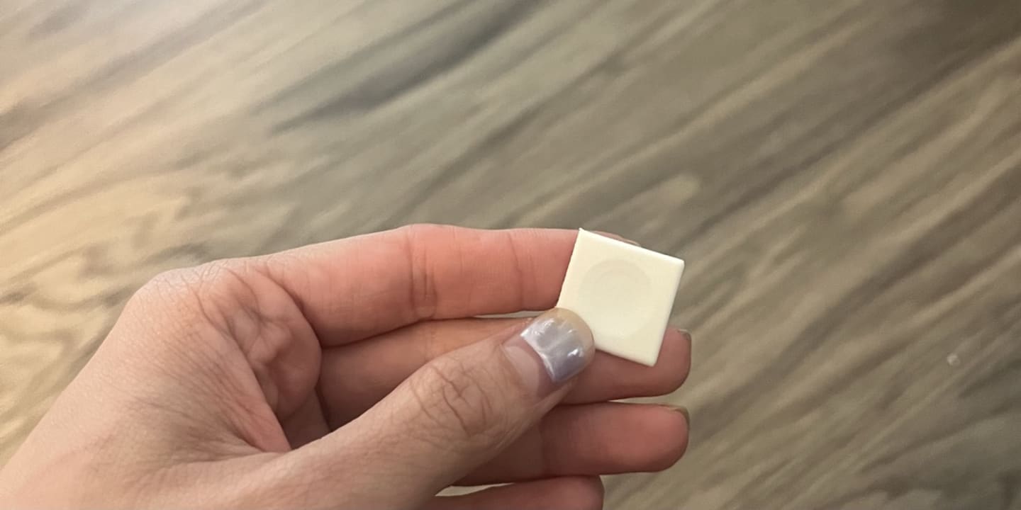
The keycaps feel nice with a dip in the center, but i’m not satisfied with the thickness.
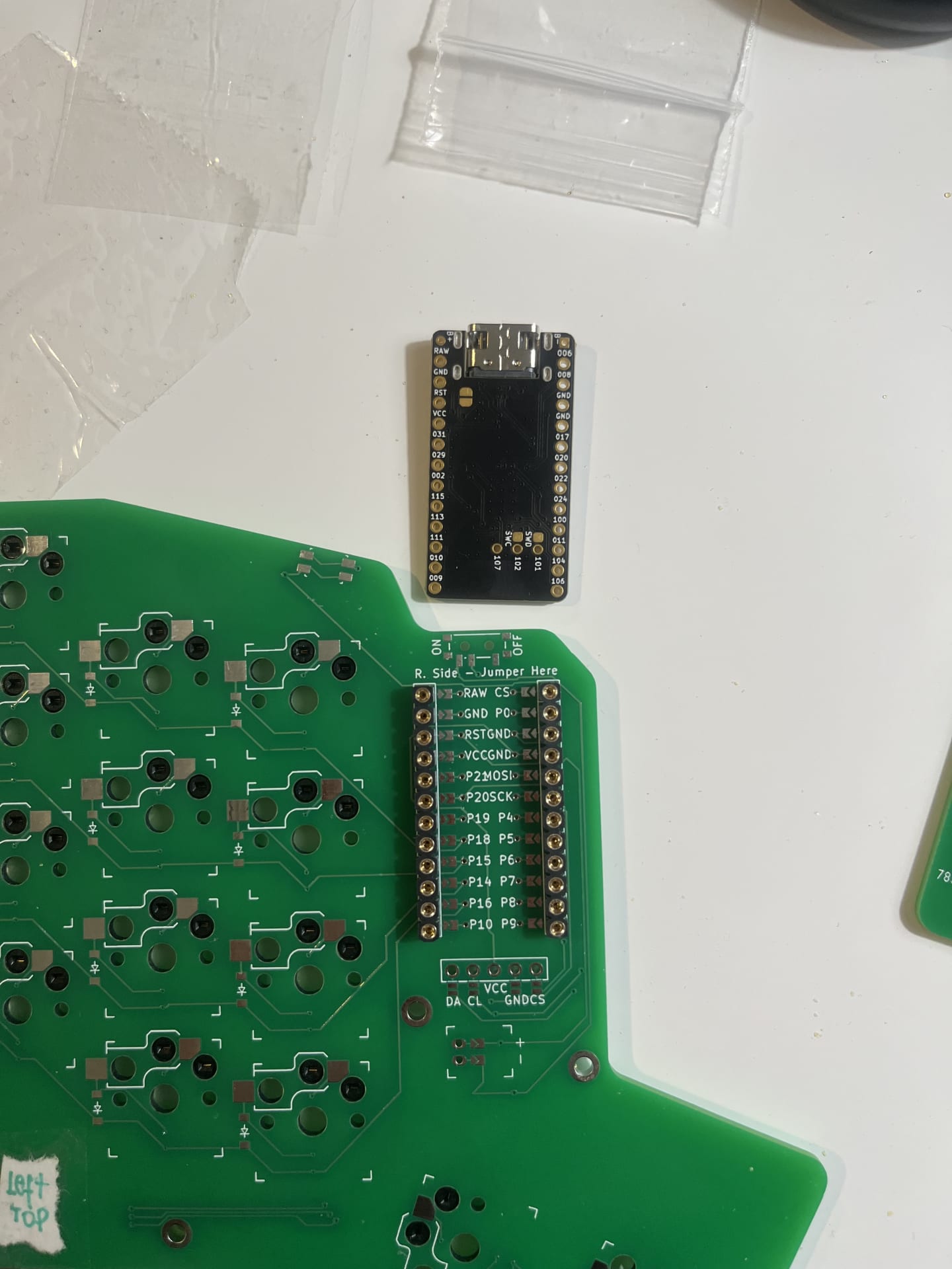
Assembling the keyboard … almost a tragedy

I’m not sure why I attempted to build this. I have no electronics background!!!! By the time I felt like giving up I decided to just push through because there was nothing else I could do anyway and I had already gotten this far.
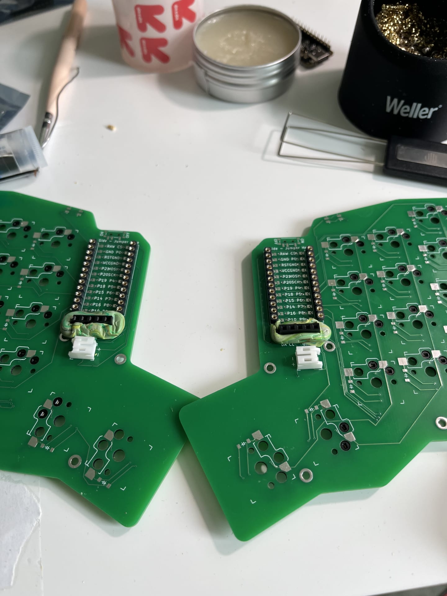
Questionable routes among other things
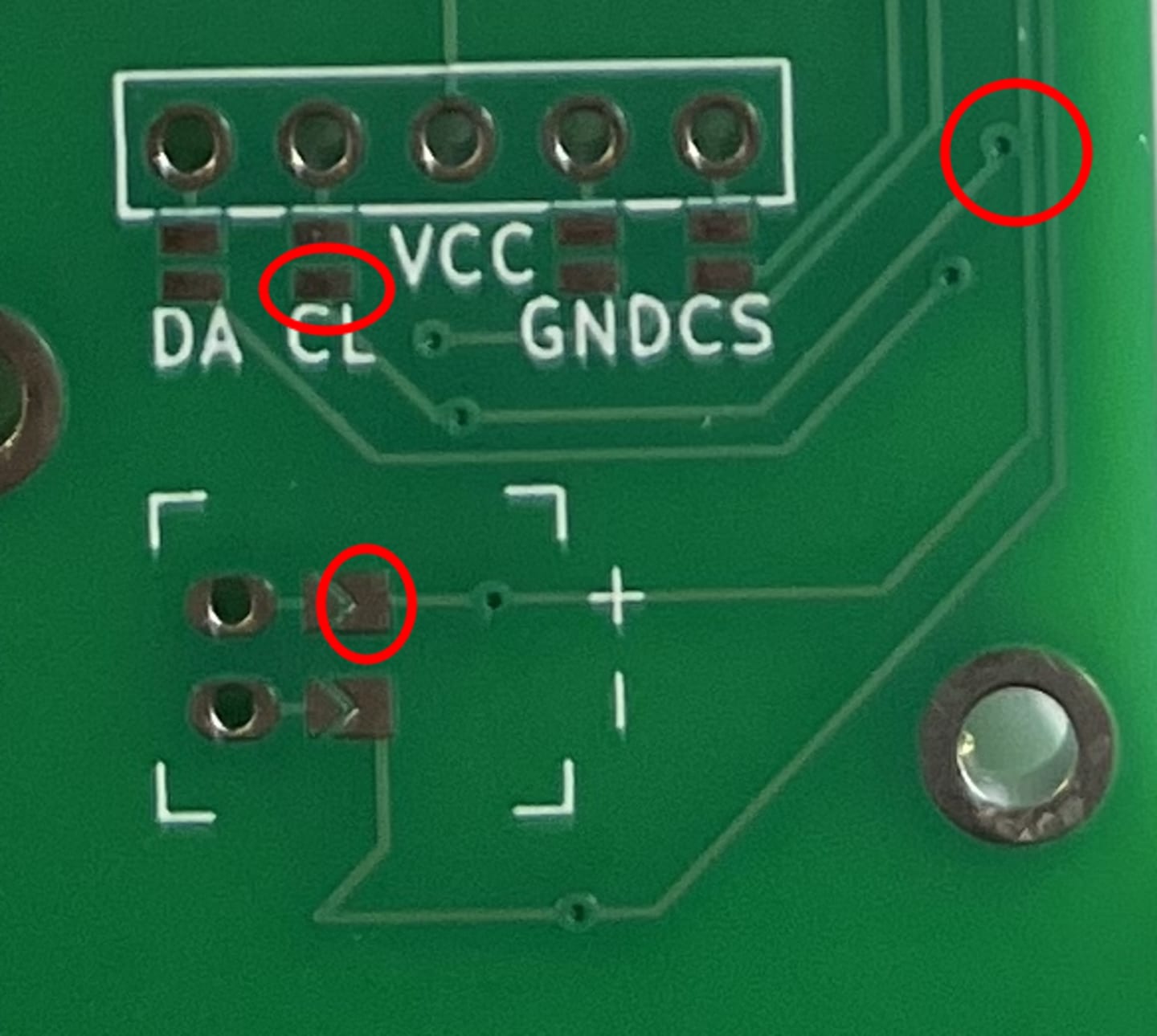
ALMOST made a huge mistake. It looked like CL was ocnnected to BATP which would have made my board unusable. I didn’t have a TRRS jack setup and my main goal was to have a wireless keyboard. Thankfully, after hours of thinking about the routes and my silks, it turned out all I had to do was to bridge the jumpers on the back to make the mcu mount as I wanted it.
I had no electrical tape so I used leftover clay from another proejct. It was actually really useful.
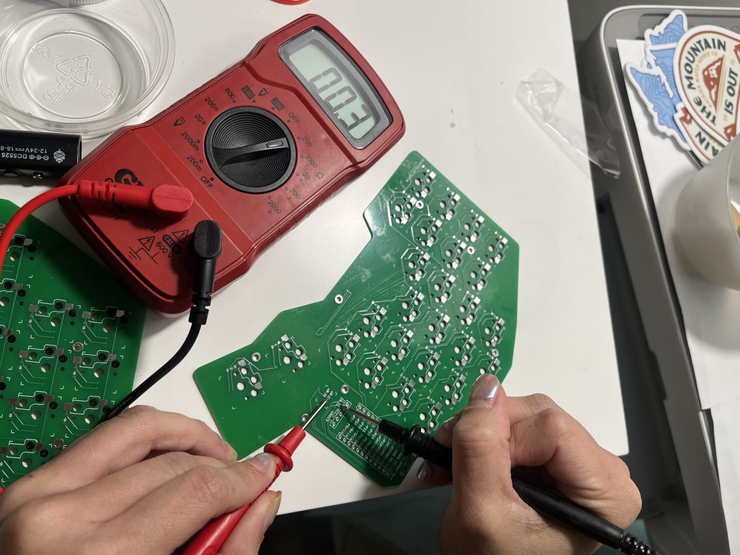
The real MVP - multimeter
I had never used a multimeter till last week. I can’t believe I was going to attempt this project without getting one. Thanks to the lovely folks at the ergogen discord, I did get one and I ended up relying on the meter over my silks.
The battery…

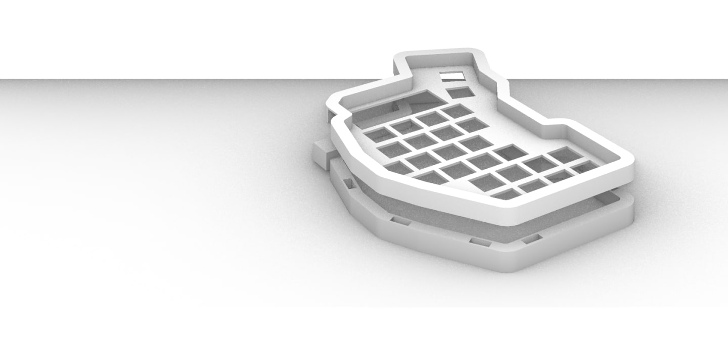
Case
Attached with magnets so I can fabricate a transportation piece and also add tenting legs.
Flashing the firmware
It was complicated but TLDR I got it working and now I can type with my keyboard!
Things to do:
- Decide minimum acceptable specs for keyboard
- Iterate over different board shapes and decide which shape is most comfortable for my hands
- Learn / use ergogen to generate output file
- Route left hand in KiCad
- Route right hand in KiCad
- Send to manufacturer
- Purchase materials
- Iterate over case designs with laser cutting and 3d printing
- Solder switches and mcu to PCB
- Assemble cases
- Write documentation
nearby